Figure 1. Basic Configuration of the DTS (Data Transmission System)
| June 15, 1999: | Draft release |
| June 17, 1999: | "Summary" and "Appendix-A Abbreviations" were added.) |
| June 18, 1999: | Error correction in Table A2-2 (tf at 64 MHz from 5 to 3)) |
| Aggregated bit rate | Number of Connectors | Clock Rate | Logical Number of Wires |
|---|---|---|---|
| 64 Mbps | 1 | 4 MHz | 16 |
| 128 Mbps | 1 | 8 MHz | 16 |
| 256 Mbps | 1 | 16 MHz | 16 |
| 512 Mbps | 1 | 32 MHz | 16 |
| 1024 Mbps | 2 | 32 MHz | 32 |
| 2048 Mbps | 2 | 64 MHz | 32 |
And we introduce a time code (IRIG-B) for VSI.
We also describe the software implementation and
illustrate the expected views of the system configurations
which will be seen in the various stages of the VLBI operations
with the use of VLBI Standard Interface.
Investigations of VSI signal definition and VSI connector pin
assignment and cable wiring are also introduced.
Finaly, our conclusions
for VSI are as follows.
| (1) | A standard VLBI recorder interface is urgently required to promote future world wide corporations in a VLBI observation and to encourage new developments for more advanced VLBI data acquisition system. |
| (2) | The clear and transparent interface makes easy to operate different types of recorder system in parallel at an observatory and at a processing site. Easy translation also becomes possible. |
| (3) | Physical specifications for input and output data, timing signals and time codes are important |
| (4) | Realization of the VSI on different types of recorders is strongly requested. |
| (5) | The VSI specifications do not exclude any ADDITVE functions but only defines MINIMUM functions. |
| (6) | In the VSI realization, any internal design is acceptable. |
| (7) | A standard software control protocol, a communication line and messages, should be defined in the final VSI documentation. |
(June 14, 1999)
| (1) | Easy translation of a tape media The DOB (Digital Output Box) output shall be connected to the DIB (Digital Input Box) in the tape translation, not only to a correlator. The output connector of the DOB shall be mated to the input connector of the DIB. |
| (2) | Tandem operation of two or more DTS(Data Transmission System)s Two or more DTSs will be involved not only in correlation but also in data acquisition. Wide band data recording at a rate beyond 1 Gbps would be made on two or more recorders. Synchronized operation of the DTS to others is a matter of concern as much in the parallel recording as in correlation processing. |
| (3) | Real time correlation Real time correlation would be a future important function of a reliable long-baseline interferometer, in which the data on a tape is always checked for the auto-correlation spectrum, cross correlated for monitoring the phase stability while the recording is carrying on. Single operation of DIB at an observatory, (and of DOB at a correlator) will be less important in future, though it would keep economical benefit on the recording (or playing back) cost. My preference is not on the separation of DIB and DOB boxes. |
| (4) | Sub network correlation Future operation of a VLBI network connecting a number of telescopes over the world will be made in sub networking. In the correlation, dynamical resetting and offsetting of ROT (Requested Observe Time) might be important. |
| (5) | Unified software support A complicated software control might cause difficulty in the operation of different types of DTS. The DTS shall be controlled under the FS9 field system following the VEX schedule file. |
The expected views of the system configurations which will be seen in the various stages of the VLBI operations with the use of VLBI Standard Interface (VSI) are illustrated in Appendix-1.
The DIB and DOB is just the same ones as described in the draft proposal VSI specification except for adding timing signals I/O on both boxes. Even in case that the DTS is divided into the DIB and DOB, the both input and output functions of the timing signals is useful for various applications to be noted later.
In this application synchronization of two or more DIBs is performed with a similar way commonly done in correlation processing.
The IRIG-B code is widely used in a time transfer system in the world. The precision of one second is enough in presumable applications to VLBI observations and correlation processings. Higher precision to the sub millisecond will easily be obtained by counting a data clock, if necessary. The second epoch is defined by a start of the coding sequence but not enough in the accuracy. The combination of an 1-pps signal and the IRIG-B time code is proposed. In an original draft of the VSI proposal the time set is assumed to be done by a computer communication. But in this case, interchangeability of a control software is difficult to provide. The combination of the 1-pps signal and the IRIG-B code makes possible to set a time automatically without any supports by a control computer. An example of the realization of such a time code transfer system is shown in Figure 5. From a clock and an 1-pps signal, an internal clock is tuned to a master clock outside, then a time code is recognized by decoding an IRIG-B code. Internal timings and arbitrary time codes on a tape are generated in a digital data processor in a DIB. The time code on the tape is reproduced at a specific epoch of a clock, then the 1-pps signal, data are generated in a processor in a DOB. By referencing the time code on a tape the IRIG-B code is generated in the encoder.
"Year" is not defined in the IRIG-B code. It is, however, not a difficult work to generate any time code including the "year" on a tape of any type by referencing to time description written on a schedule file or a log file at a time of observation and correlation processing.
Any time codes are permissible on a tape. The realization is an internal matter of a DTS. Both insertion and replacement of a time code in a data stream is acceptable.
| Aggregated bit rate | Number of Connectors | Clock Rate | Logical Number of Wires |
|---|---|---|---|
| 64 Mbps | 1 | 4 MHz | 16 |
| 128 Mbps | 1 | 8 MHz | 16 |
| 256 Mbps | 1 | 16 MHz | 16 |
| 512 Mbps | 1 | 32 MHz | 16 |
| 1024 Mbps | 2 | 32 MHz | 32 |
| 2048 Mbps | 2 | 64 MHz | 32 |
Regarding more details about signal definitions and connectors, see Appendix-2 and Appendix-3.
| Operation | Command Code | Comments |
|---|---|---|
| Recording Start Command | REC | Record |
| Playback Start Command | PLAY | Play back |
| Synchronous Record | SYNR | Record synchronously |
| Synchronous Playback | SYNP | Play back synchronously |
| Stop Command | STOP | Recorder stops and waits for a command. |
| Bit Rate Specification | BR=nnnn | Unit: Mbps Examples "nnnn=0064" : 64 Mbps "nnnn=0128": 128 Mbps "nnnn=0256": 256 Mbps "nnnn=0512": 512 Mbps "nnnn=1024": 1024 Mbps "nnnn=2048": 2048 Mbps |
| Fast Forward Command | FF | Go to a tape end |
| Fast Rewind Command | RW | Go to a tape head |
| Tape Loading | LOAD | Load a tape |
| Tape Unloading | UNLD | Unload a tape |
The control software can sense the recorder status on the items listed in Table 3.
| Items of status | Responce Code(*) | Comments | ||||||||||||||
|---|---|---|---|---|---|---|---|---|---|---|---|---|---|---|---|---|
| Transport Status |
| In recording In playing In synchronously recording In synchronously playing In fast forwarding In fast rewinding Stop and waiting for command | ||||||||||||||
| Bit Rate Sensing | BR=nnnn | Unit: Mbps Examples "nnnn=0064" : 64 Mbps "nnnn=0128": 128 Mbps "nnnn=0256": 256 Mbps "nnnn=0512": 512 Mbps "nnnn=1024": 1024 Mbps "nnnn=2048": 2048 Mbps | ||||||||||||||
| Tape Staus |
| Tape is mounted and ready to start. Tape is mounted but not ready. Tape is not mounted. | ||||||||||||||
| Tape Position |
| Tape is at the beginning. Tape is at the end. | ||||||||||||||
| Tape Remains | BEST=nn | Percent of tape rest | ||||||||||||||
| Data Status |
| Data is available. Data is not available. |
Messages listed in the Table 2 and Table 3 are minimum requested codes in a software communication. Other special commands and status items can be defined for each recording system for their own convenience. Regarding an actual communication link to be used, e.g., Ethernet, RS-232C, IEEE-488, USB, etc., and the details should be defined later.
| (1) | A standard VLBI recorder interface is urgently required to promote future world wide corporations in a VLBI observation and to encourage new developments for more advanced VLBI data acquisition system. |
| (2) | The clear and transparent interface makes easy to operate different types of recorder system in parallel at an observatory and at a processing site. Easy translation also becomes possible. |
| (3) | Physical specifications for input and output data, timing signals and time codes are important |
| (4) | Realization of the VSI on different types of recorders is strongly requested. |
| (5) | The VSI specifications do not exclude any ADDITVE functions but only defines MINIMUM functions. |
| (6) | In the VSI realization, any internal design is acceptable. |
| (7) | A standard software control protocol, a communication line and messages, should be defined in the final VSI documentation. |

| Data rate (Mbps) | Data Clock Frequency (MHz) | Number of Wire | Connector primary | Connector Secondary |
|---|---|---|---|---|
| 64 | 4 | 16 | DATA0-DATA15 | Not used |
| 128 | 8 | 16 | DATA0-DATA15 | Not used |
| 256 | 16 | 16 | DATA0-DATA15 | Not used |
| 512 | 32 | 16 | DATA0-DATA15 | Not used |
| 1024 | 32 | 32 | DATA0-DATA15 | DATA16-DATA31 |
| 2048 | 64 | 32 | DATA0-DATA15 | DATA16-DATA31 |
Proposed VSI data rate and parallel data transfer is presented in Table1. The bus width is varying two steps 16 and 32 wire. Within the width, data clock is selected to accomplish its total data rate. In Japanese case our K-4 system is 8 wired system up to 256 Mbps. For the VSI fruit, we will make an effort to change it. As for 1024 Mbps mode, the data bus width is doubled. Finally, 64 MHz clock is used to achieve 2048Mbps. We hope other VSI group will also take this simple idea.
The VSI electrical characteristics is mainly based on differential- ECL connection rules. Although other low voltage differential line drivers are appeared recently, Still the ECL is very popular among our VLBI engineer, technician and manufactures around. World-wide parts availability is another important reason to choose this. Among several ECL definition, The "ECL10K" is recommended. The "ECL10KH" is also recommended in high speed 64MHz operationfor tr and tf improvement. The timing specification of the VSI is summarized Table 2. Our basic rule to the multiple connector expansion is as follows. The clock in a connector will define a timing to determine the data in the connector. This means the primary connector clock is not used for the secondary connector vise versa. The other lines are referred from the primary connector. We have three special lines attribute the clock and data. VALID is the line which tell a DOB data validity to latter stage. This line must activate at the moment of a recorder DOB synchronize. Any DOB asked to use this line to indicate its data status. 1PPS in ECL determine precise data relation to 1-PPS. The 1PPS width tw_1pps is a Hydrogen-maser dependent. Usually this is several micro sec to hundreds micro-sec duration and we use the rising point only. Since the 1-PPS can become signal to check the system directly, conventional 1PPS using a BNC connector output is recommended in DOB. IRIG-B is an idea introduced by Kawaguchi. The IRIG-B is the only TTL signal in this VSI electrical definition. The IRIG-B is used to mark the 1-PPS tick with certain UTC. The IRIG-B is used to label each 1-PPS and issued at coarse timing itself. This serial transfer is very slow. Thus it is possible to remain it in TTL besides high speed ECL. The IRIG-B marker delay to the 1PPS will be around 2-ms. (Please refer our main draft proposal.)
| CLOCK (MHz) | tc(ns) | td(ns) transmit side | Tw(ns) | tr(ns) 20-80% | tf(ns) 80-20% |
|---|---|---|---|---|---|
| 4 | 250 | 125 | 125+/-3 | 5 | 5 |
| 8 | 125 | 62.5 | 62.5+/-3 | 5 | 5 |
| 16 | 62.5 | 31.25 | 31.25+/-3 | 5 | 5 |
| 32 | 31.25 | 15.625 | 15.625+/-3 | 5 | 5 |
| 64 | 15.625 | 7.8125 | 7.8125+/-3 | 3 | 3 |

| Name | Number | Purpose |
|---|---|---|
| CLK | 1 | Data clock |
| DATA 0-31 | 32 | Data |
| VALID | 1 | inform data validity |
| 1PPS | 1 | 1PPS tick |
| IRIG-B | 1 | Separate coarse time code |
| Total | 37 | �cneed more than 74 metal lines |
Currently the required lines for the VSI data transfer based on Whitney and Japanese group documents are summarized in Table A3-1. Since cable / connectors more than 50 wire is not common, and even in our VSI application VLBI mode below 256 Mbps will remain certain period. To implement the idea to the cable and connectors available, a compromise with multiple cable and connector is our choice. The concept which uses two cable in high speed data rate are reasonable. The cable is 20-set of twisted pair cable assembly. On the other hand there is no compromise with cable electrical structure. Due to the cross talk and external effect, 64 MHz clock data transfer without the appropriate shield will be a troublesome part. For the high speed data transfer, each twisted pair are shielded as in Figure A3-1. In Table A3-2, reduced lines to a connector is shown. When we separate data to connectors, data clock should supplied separately to eliminate cable uncertainty among the cables.
| Name | Number | Level | Purpose |
|---|---|---|---|
| CLK | 1 | ECL | Clock rise timing determine data valid point In each connector |
| DATA 0-15 or DATA 16-31 | 16 | ECL | Data separated 16 lines each. Low speed data need only one connector. |
| VALID | 1 | ECL | Flag which used to check stream data validity to latter stage. For an example correlator will use this flag as a DOB synchronization. Recorder DOB will use this flag as servo lock. |
| 1PPS | 1 | ECL | Tick rise point define a certain data point k to station H-UTC. (From a view of In/Output transparency, An additional 1PPS output using BNC connectors TTL level is recommended in case of DOB.) |
| IRIG-B | 1 | TTL | Coarse time code give the 1 PPS tick to certain H-UTC. Please refer Japnese group draft poroposal. |
| Total | 20 | 40-pins are used for signal. Remaining 10 are used for shielded grounds | |
| Pin | name | Pin | name | Pin | name |
|---|---|---|---|---|---|
| 1 | CLK+ | 18 | GND | 34 | CLK+ |
| 2 | DATA0(16)+ | 19 | GND | 35 | DATA0(16)- |
| 3 | DATA1(17)+ | 20 | VALID+ | 36 | DATA1(17)- |
| 4 | DATA2(18)+ | 21 | VALID- | 37 | DATA2(18)- |
| 5 | DATA3(19)+ | 22 | RESERVED | 38 | DATA3(19)- |
| 6 | DATA4(20)+ | 23 | RESERVED | 39 | DATA4(20)- |
| 7 | DATA5(21)+ | 24 | GND | 40 | DATA5(21)- |
| 8 | DATA6(22)+ | 25 | GND | 41 | DATA6(22)- |
| 9 | DATA7(23)+ | 26 | GND | 42 | DATA7(23)- |
| 10 | DATA8(24)+ | 27 | GND | 43 | DATA8(24)- |
| 11 | DATA9(25)+ | 28 | IRIG-B | 44 | DATA9(25)- |
| 12 | DATA10(26)+ | 29 | GND(IRIG) | 45 | DATA10(26)- |
| 13 | DATA11(27)+ | 30 | 1PPS+ | 46 | DATA11(27)- |
| 14 | DATA12(28)+ | 31 | 1PPS- | 47 | DATA12(28)- |
| 15 | DATA13(29)+ | 32 | GND | 48 | DATA13(29)- |
| 16 | DATA14(30)+ | 33 | GND | 49 | DATA14(30)- |
| 17 | DATA15(31)+ | | | 50 | DATA15(31)- |
| *() for secondary connector name | |||||
The pin assignment to the D-sub 50 pin connectors is presented in Table-A3-3. The pin assignment is already used by Philips and Panasonic in their digital equipment. This means the connector assembly with the cable and panel-adapter mount to a printed circuit board is established. Only the CLOCK, DATA_n, VALID, 1PPS and IRIG-B are commonly used signal in the VSI. At this moment one reserved line are remained for furthur requirement. But other data line depends particular DAS, DIB, DOB or correlator hardware are not allowed to appear in the VSI connection. Using carefully shielded cables and enough ground pin remaining in the 50pin, the multi-vendor environment connection will become stable and successful. Currently experiment using the cables are prepared at CRL.
The D-sub connector shell should use ISO bolts and nuts for mechanical compatibility.
 |  | 
|
| Figure A3-3. Flat cable. | Figure A3-4. ID1 cable | Figure A3-5. ID1 & VSI |
VLBI data transfer had been using differential ECL signals and twisted pair cables. Figure A3-3 shows flat cable with and without shield. Figure A3-4 shows D-sub25 connector and cable used in the Japanese K-4 VLBI. The assembled cable is also consist from twisted pairs and an assembly shield. These cables are enough performance below 32 MHz data clock rate. But above the 32 MHz and multi vendor environment expected in the VSI, exact ECL signal shape must be maintained under higher clock. The IVS-TDC CRL group experienced parallel 128 MHz ECL data transfer will cause terrible data degrade with slight cable difference. We strongly propose to employ twisted pairs with shielded each for 64 MHz expansion. Although this will increase the weight of cables, the de-factory standard cable for the D-sub 50 like in Figure A3-5(left) exists, the assembly employed AWG27 equivalent conductor is diameter of around 15 mm and reasonable price. If a special cable is designed for VSI, it will drastically increase its cost and they are difficult to obtain replacement one.
As for a connector, The connector shell and connector latch mechanizm expected be have enough stiffness to support the cable weight. The D-sub with screw bolt is preferred. VLBI equipment are connected and disconnected often on site. Also it important the on site engineer can inspect signals directly. Others new connectors are too small to handle and often weak. It is better to employ D-sub 50 for the VLBI purpose.
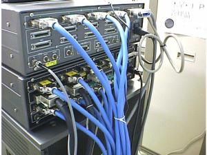
Figure A3-6 shows succeeded Japanese 1024 Mbps VLBI system interface which uses four ID1(256 Mbps) cables currently . This is very confusing in cable arrangement. We will adapt our interface to the VSI standard when they are determined.
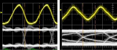
An example of ECL clock / data quality at transmission and reception point is shown in Figure A3-7. This is the worst case established connection at 64 MHz. The amplitude of signals are reduced. The shape of signals are far from ideal condition at the reception point (right) We should not think little of cable in VSI.
| Connector Common Name* (pin) | Figure | Approx size Panel cross section (mm) | Combination assembly with shielded long cable (20meters) | Price in Akihabara | Application, reputation and history. |
|---|---|---|---|---|---|
| D-sub (50 pins) |  | 65x14 | YES | $12-$20 | Good reputation and long history. Large price dynamic range. D-sub 25 is very popular. Easy to check pin signal on site. |
| D-sub half pitch (50) |  | 52x11 | Unknown,Latch seems poor to support shielded cable weight of 15 mm diameter | $10 | SCSI, no long history. A CRL VLBI Giga-bit correlator use the connector at 32MHz with cable less than 2-meters. From our experience, less reliability than D-sub. |
| AMP Centronics (50) |  | 80x15 | YES | $15 | Printer, computer, Share decreased. due to huge connector size and repeatability. |
| AMP Centronics Half pitch(50) |  | 40x10 | Unknown,Latch seems poor to support shielded cable weight | $18 | SCSI |
| DIN VME (64) |  | 95x11 | Possible, huge connector size. No connector latch. Friction only. | $15 | VME, cable connector available. Occurs poor contact in certain manufactures connector combination. |
| MIL Flat cable |  | 68x6 | Plastic latch poor to support shielded cable weight | $5 | Computers, very popular cheap. |
| DAS | Data Acquisition System |
| DIB | Digital Input Box |
| DTS | Data Transmission System |
| DOB | Digital Output Box |
| DOT | Data Observe Time |
| ROT | Requested Observe Time |
| VSI | VLBI Standard Interface |