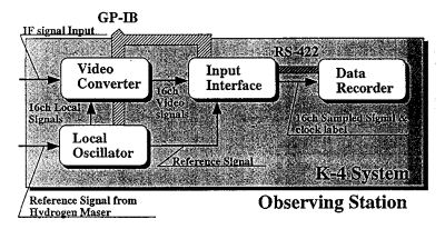
Figure 1. Observing station.
The K-4 VLBI system is being developed at CRL as the next-generation system. In this system a rotary-head cassette recorder (American National Standard 19 mm Type ID-1 Instrumentation Digital Cassette Format) is used to make the system smaller and easier to operate. The interfaces are designed to be compatible with that new recorder. Two interface units are used to obtain compatibility with other VLBI equipment: an input interface unit between the video converter and the recorder and an output interface unit between the recorder and the data processing system. We are making a more compact system with observational functions and data processing functions housed in separate units. The K-4 system consists of the following; (1) local oscillator. (2) video converter, (3) input interface unit, (4) output interface unit (5) data recorder.
The block diagrams are shown in Figs.1 and 2. The local oscillator synthesizes the local frequency signal for the video converter. The video converter converts a window in the IF signal (lOO-500 MHz) input to a video signal (0-2 MHz). The frequency conversion is achieved by the image rejection mixer using single-sideband conversion. These functions are equivalent to the IF distributor, video converters (16ch) and reference distributor of the Mark-III or K-3 VLBI systems.
The input interface unit is used for data acquisition and recording at the VLBI observing station (Fig.1). It samples the video signal from the video converter, and sends the digital data to the data recorder together with the time data which is derived from the external time standard signal.
The output interface unit is used at the correlation station (Fig.2). It converts the reproduced data into the appropriate output format, and sends them to the correlator. The format of the output interface unit is compatible with the Mark-III format. Besides this format, another format is also provided for future correlator systems; this provides only digitized raw data signals. When multi-baseline correlation is processed, all the output interface units are daisy-chained through GPIB, so that the tape position data and status data of all the data recorders can be exchanged. The main (reference) output interface supplies the timing clock to sub-output interfaces. The delay bit between the main and sub-output interface units is calculated in each sub-output interface unit, using the time data which is periodically inserted into the recorded data.
It is possible to interface with current VLBI systems through the above-mentioned two interface units. Input and output interface units, when connected together directly, also perform a function equivalent to the formatter of the K-3 VLBI system.
Due to the development of technology, VLBI is now used for more varied purposes and its observing stations are not only fixed ones but mobile ones used in remote islands and in Antarctica
