Communications Research Laboratory
4-2-1 Nukui-kita, Koganei, Tokyo 184-8795, Japan
Abstract: We have developed a new VLBI system based on the conventional K-4 system. The
system was designed to achieve automated operation throughout the entire
process, it is operated one operator for observation arrangement and correlation
processing. The KSP system has two data transfer systems, one is a tape-based
system and the other is a real-time system. The new acquisition system is
designed to interface both systems, the two systems are possible to be operated
simultaneously. The new acquisition system has multi-bit quantization sampling
modes. The total data rate is up to 256 Mbps, and up to 16 video channels can
be selected. Filterings are carried out in the digital filter. The digital
filter is used because it results in good phase characteristics. This system is
specially designed for the Key Stone Project, and an input interface unit is
incorporated in the VSOP.
1. The New K-4 System
The KSP data-acquisition system (Figure 1), a high-end version of the K-4 system
[Kiuchi et al., 1997], has a maximum recording rate of 256 Mbps and is
fully automatic. The different features of the systems are given in Table 1.
The data-acquisition system consists of a reference distributor, IF distributor,
local oscillator, video converter, input interface, output interface, data
recorder, and digital mass storage system (automatic tape changer). The local
oscillator synthesizes the local frequency signal for the video converter
(Figure 2). This video converter converts windows in the IF-signal (500-1000
MHz) input into video signals. The frequency conversion is done by a image
rejection mixer using single-sideband conversion. The output interface unit is
used at a correlation processing station for tape-based VLBI.
Figure 1. Block diagrams of the new K-4
(observing station configuration).
Figure 2. Block diagram of the new K-4 video
converter and local oscillator.
Table 1. The different features of K-4 systems and other VLBI systems.
1.1. Input Interface Unit
The input interface unit samples the video signal from the video converter
(16-channel max.), and sends the digital data (256 Mbps max.) to the data
recorder and/or the ATM transmitter (for a real-time VLBI system: in this
issue) together with the time data. A block diagram of the input interface unit
is shown in Figure 3. The acquisition system has one-bit and two-bit sampling
modes for VLBI, and also has 4- and 8-bit sampling modes for general-purpose
data acquisition. The anti-aliasing filtering is done in analog (32 MHz), and
after sampling, the 16-MHz, 8-MHz, etc. filtering is done by the digital
filter. The advantages of using the digital filter are that it can obtain good
phase characteristics and can reduce coherence loss for wide bandwidths.
Suitable coefficients of the digital filter can be selected for each
observation; for example, the digital filter is used as a bandpass filter for
the line observation. The coefficients of the basically lowpass filter needed
for Nyquist sampling are provided in the read-only memory (ROM). The output
rate of data to the recorder or the ATM transmitter can be selected from five
rates ranging from 16 to 256 Mbps. Time-code insertion can be at uniformly
bit-space or at uniformly time-interval, or no time-code can be selected. In
real-time VLBI, an uniformly bit spaced time code is used, as required by the
ATM side. The suitable quantization threshold level of the A/D converter is
adjustable. The configuration for one- and two-bit sampling is shown in Table
2. This input interface can be interfaced in analog to the Mark-III system with
no modifications, using some BNC cables. This input interface is incorporated
in the VSOP (VLBI Space Observatory Program).
Figure 3. Block diagram of the new K-4 input interface.
Table 2. New K-4 data configuration
* = Mark-III mode, ** = VLBA mode, vs = VSOP mode.
1.2. Data Recorder
We adopted a rotary-head type recorder that uses a cassette tape, which uses the
ANSI (American National Standards Institute) X3.175-1990 ID-1 format. The data
recorder's error rates during recording and replaying can be read through a host
computer. Helical-scan recording is used to record high-rate digital signals.
With a large cassette, the K-4 recorder provides up to 770 Gbits of data-storage
capacity. The recording time is 200 min. (large cassette, 16-mm thick tape),
with a 64-Mbps recording rate. Recording and playback are possible at different
data rates: 256, 128, 64, 32, and 16 Mbps, making the data recorder suitable
for many different applications. The playback heads are placed so that the
recorded data are immediately played back during recording. This
read-after-write facility makes it possible to monitor the error conditions of
recording in real time. The bit error rate after correction was better than
1x10⁻¹⁰. The data recorder employs a built-in diagnostic system, which is
designed to detect operation errors or hardware faults. Error messages or
warning information is fed to the host computer via the remote control
interface, and to the front panel display. The periodicity of the time code is
undesired for spectrum analysis. Only the sampled raw data are desired. The
K-4 recorder has helical data tracks, two longitudinal annotation tracks and a
control track (Figure 4). The VLBI data are recorded on the helical data tracks.
A set of four helical data tracks has one track set ID number, which is a
sequential number as a tape counter. The track set ID numbers are recorded on
the control track, and can be read at any tape speed, even when fast forwarding
or rewinding. There is an obvious relationship between the track set ID and the
time code, and it is possible to manage the time code under the track set ID and
time code block. The time data are written over the data train as the time code
block in pre-observation. After the time-code block, the data timing is checked
by track set ID, which means that the output data are only raw data digitized
during observation. A data format fully compatible with the conventional K-4
system is also provided.
Figure 4. Tape format and data format.
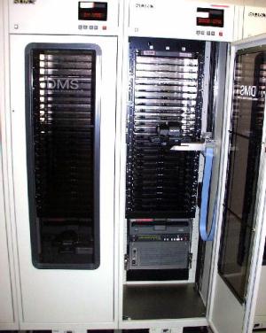
1.3. Digital Mass Storage System (Automatic Tape Changer)
In KSP, we adopted an automatic tape changer as a digital mass-storage system
(Figure 5). The system accommodates one tape drive and 24 tapes, or two tape
drives and 16 tapes. The mass-storage capability is up to 2.3 TB. A barcode
reader is built into the cassette-handling system to identify individual
cassettes within the mass- storage system. Information from the barcode reader
is available to the host controller via the remote control interface, and is
written on the log which is utilized for correlation processing.
Figure 5. Digital Mass Storage System (Automatic Tape Changer).
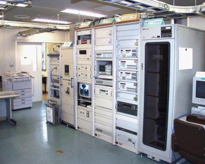
2.1. View of the data acquisition system
A photograph of the data acquisition system is shown Figure 5. From left side,
an ATM transmitter, an weather monitoring rack, an antenna control rack, a
receiver control and monitoring rack, a backend rack, a digital mass-storage
system. Three IF signals are received by IF receivers in the receiver control
and monitoring rack. The IF signals send to an IF distributor in the backend
rack. The two sets of video converters (500 -- 1000 MHz : 8 ch/unit) converts
IF signal to video signal. And the other video converter (100 -- 500 MHz : 16
ch/unit) is prepared as a conventional K-4. The video signals are send to the
input interface (black panel), and the digital data is send to the digital
mass-storage system. The data is recorded on the magnetic tapes, or by-passed
to the ATM transmitter.
Figure 6. View of the data-acquisition system.
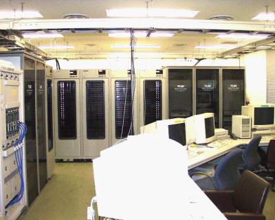
2.2. View of the correlation processing room
A photograph in Figure 6 shows the view of the correlation processing room.
We
have two correlation processing systems, one is tape-based system (front) and
the other is real-time system (left side).
In the tape-based system, left side
are digital mass-storage systems, and right side are correlation processor
racks. In KSP, there are four sets of digital mass-storage systems, and
6-baseline correlators. The output interfaces are upper side, the correlators
are lower two units in each correlation processor rack, and other parts are
blank panels. It is possible to extend 10-baseline correlation system with
these three racks. The tapes are loaded to or unloaded from the data recorder
(lower side) automatically by digital mass-storage systems.
Figure 7. View of the correlation processing system.
Reference
Kiuchi, H., J. Amagai, S. Hama, and M. Imae, K-4 VLBI data-acquisition system,
Publ. Astron. Soc. Japan, 49, 699--708, 1997.