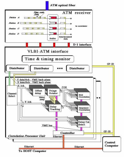
Figure 1. Block diagram of the real-time VLBI system.
Communications Research Laboratory
4-2-1 Nukui-kita, Koganei, Tokyo 184-8795, Japan
Abstract: We have developed a real-time VLBI system that uses a high-speed ATM (asynchronous transfer mode) network. In this real-time system, observed 256-Mbps/station VLBI data is transmitted through a 2.488-Gbps ATM communication network [STM-16] instead of being recorded onto magnetic tape. The system was specially designed for the Key Stone Project (KSP), which is concerned with measuring crustal deformation using four stations in the Tokyo metropolitan area in Japan. Cross-correlation processing and data observation are carried out simultaneously, and it takes about two hours to analyze crustal deformation data after the VLBI observation is completed. In regular geodetic VLBI experiments every other day lasting 24 hours, horizontal position uncertainty of about 1 mm and vertical position uncertainty of about 10 mm have been achieved. With the real-time VLBI system, one operator can handle both the observation and the correlation processing. The system was designed to enable automated operation throughout the entire process, and the obtained results are open to the public via the Internet (http://ksp.nict.go.jp).
A block diagram of the real-time VLBI is shown in Figure 1. The ATM network transmits information in fixed-length packets called cells. A cell (AAL type 1) is composed of 53 bytes of data in total, a 5-byte header and a 48-byte payload but 1-byte is used as a sequence number to check for cell loss and mis-delivery. The signals input to the ATM transmitter are written in the payload of the ATM cell in arrival order. The header of the cell, which shows its destination, is attached when the payload becomes full, and the cell is output to the 2.488-Gbps transmission path [STM-16]. In the KSP real-time VLBI system, the signals from the four stations can be transmitted along one transmission path, and a cross-connect switch connects the multiple transmission paths. In the receiver, the multiplexed signal (cells) is separated into the data for each station and cells are disassembled and restored as digital signals after the destination in the header data is checked. The real-time VLBI system also has functions that compensate for delay, absorb cell-delay fluctuations in the transmission system, and compensate for mistaken cell delivery and cell loss in the receiver. In real-time VLBI, the data from each station is data synchronized in the receiver (Figure 2). To absorb the transmission-path delay, the signal begins to accumulate in the buffer memory from the time the time stamp (every 64 Mbit) is received. This time code is generated by the input-interface [Kiuchi et al., 1997]. The readout for the buffer memory starts immediately after the time stamps from all observation stations have arrived allowing the timing to be synchronized. Because the data is output to the correlator after the timing has been synchronized, the output data for each station is correct up to the time on the time stamp. The KSP correlation processor is an XF type that uses field programmable gate arrays. The maximum processing data rate is up to 512 Mbps.
Sato, K., S. Ohta, I. Takizawa, Broad-band ATM network architecture based on virtual
paths, IEEE Trans. Commun., 38, 1211--1222, 1990.