Geodetic Department,Geographical Survey Institute, Ministry of Construction
Kitasato 1, Tsukuba, Ibaraki 305-0811, Japan
2
Geography and Crustal Dynamics Research Center
Geographical Survey Institute, Ministry of Construction
Kitasato 1, Tsukuba, Ibaraki 305-0811, Japan
Introduction
This report summarizes the specification of Tsukuba 32m VLBI station at the
Geographical Survey Institute (GSI). We present our history of VLBI activities and
the status. First of all, GSI developed three mobile VLBI systems and had repeated
observations with CRL. In 1998, GSI constructed a domestic VLBI network with five
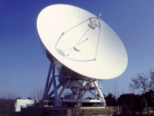
permanent stations. A main station of the network is Tsukuba 32-m VLBI station (Fig.
1). It also becomes a key station in the international VLBI networks, especially in Asia.
Figure 1. Tsukuba 32m VLBI antenna.
Antenna
Tsukuba station has a 32 m cassegrain parabolic antenna, which is made by NEC
Co. All of components are painted white color to protect the deformation by the
imbalance of temperature from sunshade. The main reflector is covered with thermal
insulator panels, then its temperature is kept between +/-3 degrees by using a
ventilation system in the back structures. The antenna structures have covers to
avoid direct sunlight. Table 1 shows the specification of the antenna, such
as the slewing speedand limit angles.
Table 1. The specification of antenna
Year of Construction
1998
Radio Telescope
cassegrain
Mount
Az-El
Diameter of Main ref.
32 m
Surface Contour of ref.
+/-0.5 mm
Azimuth Velocity
3 deg/s
Elevation Velocity
3 deg/s
Azimuth Limit
10 - 710
Elevation Limit
5 - 88
Table 2. Station Configuration
8 letter
TSUKUB32
2 letter
Ts
DOMES
21730S007
CDP
7345
Approx. Pos
X (m)
-3957408.8
Y (m)
3310229.3
Z (m)
3737494.8
Lat (deg.)
36.1031
Lon (deg.)
140.0887
Hight (m)
44.7
X-Band Tsys
50 K
S-Band Tsys
75 K
X-Band SEFD
300 Jy
S-Band SEFD
360 Jy
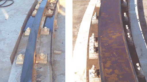
Azimuth angle of the antenna is controlled by a wheel and track system. The
original azimuth rails, which weigh 73 kg per meter and are 10 cm wide, was cracked
because the stress between wheel and rail was larger than our assumption. In April 1999,
the rails have been replaced with larger ones (Fig.2).
Figure 2. The replaced rail (Left: before, Right: current).
For the moment, the significant
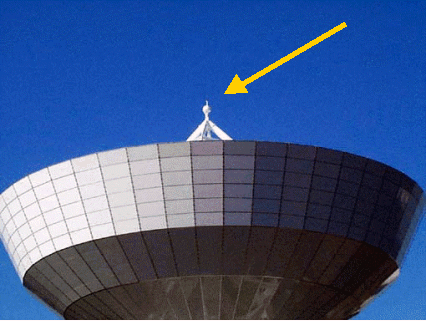
problem of the rail has not happened again. On the top of antenna, which is above
subreflector, a GPS antenna (Fig.3) is attached for the purpose of tie survey and
collocation.
Figure 3. The replaced rail (Left: before, Right: current).
Table 3 shows front-end frequencies of Tsukuba 32m antenna. A cooled
HEMT receiver which was made by Nitsuki Co. was installed in X-band. First
local PLOs, which were made by CTI LTD., were installed. However, the phase
of the PLOs were unstable worse than a thousand degree per day due to change
the temperature variation in the front-end room. We installed a cover rack
for PLOs, and the PLOs are now always cooled by Peltier cooling system to
minimize effects by the temperature variations of the outside air. Three
intermediate frequencies (IF) at X-band were installed there.
Table 3. The front-end frequencies at Tsukuba station
Input (MHz)
S band
X1 band
X2 band
X3 band
2100-2500 2120-2360 (BPF)
7780-8280
8180-8680
8580-8980
PLO1 (MHz)
1600
7280
7680
8080
PLO2 (MHz)
2000
7680
8080
8480
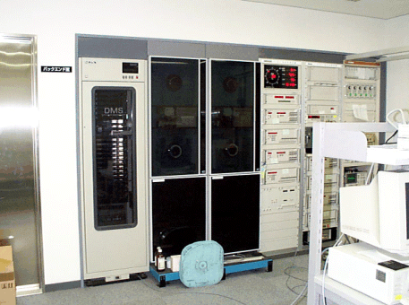
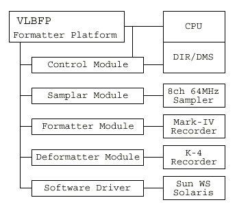
Back-end
From front-end to back-end, signals are transmitted by optical fibers to avoid the
power loss. But we have troubles with the optical fibers since they often fails
to operate recently. We are now investigating the cause of the troubles. Mark IV and
K-4 systems have been installed there. We can record with both systems simultaneously.
Figure 4. Back-end equipment.
Others
Two control systems have been installed in the station. One is the Field System
version 9 (FS9) developed by NASA GSFC. It is used for international experiments with
the Mark IV system. Another is the workstation GAOS (WS-GAOS) developed by CRL and
GSI. It is used for domestic experiments with the K-4 system. Recently, we can also
use the FS9 for domestic experiments because it now supports K-4 systems by a
cooperation with CRL Kashima and NASA GSFC.
Since 1999, a copy system, which can copy data from K-4 tapes to Mark-IV tapes,
has been installed to translate the data recorded at the stations only with the K-4
system.
Figure 4. The diagram of copy machine (from K-4 to Mark-IV).