Figure 1. Dimension of CLNA with swivel bracket.
|
Kashima Space Research Center Communications Research Laboratory 893-1 Hirai, Kashima, Ibaraki 314-0012, Japan |
Abstract: In Kashima 34-m radio telescope, we replaced an ambient 5 GHz LNA to a newly developed portable cryogenically cooled low noise amplifier made by MITEQ. Radio telescopes purpose is detection of the weak noise signal from the space as clear as possible. But signal from external objects are much lower than noise originated by receiver itself. Good signal to noise ratio (SNR) is the most important both in single dish observation and interferometric (VLBI) observation. To realize good SNR receiving system, Helium gas Cooled LNA system are used for radio astronomy observatory in general. Those cryogenic systems have performed excellent result especially in cm and mm wavelength observation. But physical and economical reason, installing those cryogenics system is not possible in all telescopes. We report installation process and first result of portable cryogenic cooled low noise amplifier.
Seek for better 5 GHz receiver performance with reasonable cost and labor, we choose portable cryogenically cooled LNA made by MITEQ. The uniqueness of cooled LNA unit (hereafter, CLNA) is closed cycle cryogenics and amplifier system integrated into compact size (309.4x189.7x258.6 (mm)). The power supply is +24V DC 6A, and there is no need of external gas supplying which simplify receiver installation.
Figure 1 shows dimension of the CLNA with a swivel bracket. There is master switch and amplifier switch in front panel that turned on powers cryogenics system and amplifier. RF input and output SMA connector are in the front panel. There is temperature controller in the front panel. Both the desired temperature and actual temperature are displayed. Monitoring the temperature via RS422 port is also possible.
| Frequency (GHz) | 4.7 | 4.8 | 4.9 | 5.0 |
| Gain (dB) | 41.5 | 41.4 | 41.2 | 41.1 |
| VSWR IN | 1.42 | 1.43 | 1.58 | 1.43 |
| VSWR OUT | 1.68 | 1.67 | 1.65 | 1.63 |
| Noise Figure (dB) | 0.35 | 0.35 | 0.34 | 0.34 |
Figure 2 shows configuration of CRL noise figure measurement. The terminator is connected to the CLNA input using 25 mm semi-rigid cable which insertion loss measured 0.16 dB. The CLNA output is amplified at a post amplifier (Gain=14.73 dB, NF=1.3 dB) then measured by a spectrum analyzer HP8563E, each components are connected with 1000mm low loss coaxial cable (insertion loss = 1.17 dB at 5 GHz). Data acquisition PC is connected to the spectrum analyzer, each measurement data was stored in PC and calculated.
The CLNA and ambient LNA measurement was carried out for comparison. The CLNA
temperature controller was set 123 K and operated continuously before
measurement. During the measurement, room temperature was 299 K. Measured
powre level generated from the ambient terminator is defined as Hot (Ph) 299
K. Then the terminator was immersed in liquid nitrogen, temperature of the
terminator is considered approximately 78 K and this measured noise power level
is defined as Cold (Pc). The NF is calculated from both levels in each
frequency from 4500 MHz to 5000 MHz. Y factor is ratio of measured HOT and COLD
signal level and is expressed as follows.
| Th | = | physical temperature of HOT terminator |
| Tc | = | physical temperature of COLD terminator |
| Tattn | = | attenuation of the 25 mm semi-rigid cable (dB) |
| Td | = | physical temperature of the 25 mm semi-rigid cable |
Figure 3 shows the measured NF of the CLNA and the ambient LNA near 5 GHz band. The power gain of CLNA in 4.8 GHz band is measured 40 dB. The NF of post amplifier and cable loss after CLNA RF output is ignorable in the CLNA measurement. From our measurement, the noise temperature of the CLNA and former ambient LNA were 27 K and 100 K. These are converted to NF 0.4 and 1.3 dB respectively. The CLNA shows improvement of noise performance. The MITEQ data provided in Table 1 and the result of CRL absolute well agreed.
In spite of same temperature setting, displayed case temperature controlled by closed cryogenics is slightly different between MITEQ and CRL measurement. According to MITEQ Inc. it takes approximately 2 hours to refrigerate the LNA to reach 123 K. In CRL measurement, the LNA temperature displayed 126 K minimum and it was not reached 123 K during operation. MITEQ Inc. informed us this is due to high room temperature under operation. However, difference 3 K was not critical in NF measurement result.
There was slight temperature variation in tilted CLNA. When the CLNA tilted a few degree toward "face-down" direction, temperature display decrease 2 to 4 K from 126 K. According to MITEQ Inc. it is due to attachment of sensor, cooled LNA temperature is not affected.
The antenna feed room is tilt depend on elevation angle (zenith to horizon). The swivel bracket has designed to keep the CLNA level regardless of elevation angle. The swivel bracket is consisting of ball bearing "swivel" with aluminum flame, which is attached with tilted connecting stay. The stay is fixed to the antenna to keep room for the CLNA moving freely in any elevation angle.
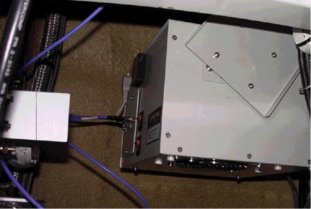
Figure 5 shows photograph of the installed CLNA on Kashima 34-m antenna. A power supply which maximum current is 10 A is closely located. Considering to keep the CLNA moving freely in any elevation angle, between waveguide-coaxial adapter and CLNA RF input is connected by flexible coaxial cable (1000 mm), measured insertion loss is 1.17 dB. The CLNA RF output to down converter input is connected same cable.
| | Ambient LNA | CLNA |
| TLNA (K) | 100 | 27 |
| TA (K) | 27 | 80* |
| Tsys (K) | 127 | 107 |
| SEFD - Cas-A (Jy) | 626.9 (1999/12/08) | 633.7 (2000/04/12) |
Table 2 shows current summery of the CLNA and the ambient LNA installed in Kashima 34-m antenna 5 GHz receiver system.
Measured performance of 5 GHz receiver system using the CLNA is showing little
improvement.
Antenna system temperature (TA) is defined following equation
[Kraus, 1986].

Figure 6 shows phase variation plot of the CLNA C-Band RX system using phase calibration signal which is injected into system by cross guide coupler. There is slow phase rotation which is considered due to room temperature variation affected by air conditioning system. However, this slow phase rotation is not serious concern for interferometric (VLBI) observation.