 News & Info
 Videos
 Access
 Contact

 Instagram

 View on Twitter

Access
Headquarters
(Koganei, Tokyo)
Kashima Space
Technology Center
(Kashima, Ibaraki)
Wideband InterNetworking Engineering Test and
Demonstration Satellite(WINDS)
 HOME
>
Research Projects
>
Wideband InterNetworking Engineering Test and Demonstration Satellite(WINDS)
HOME
>
Research Projects
>
Wideband InterNetworking Engineering Test and Demonstration Satellite(WINDS)
Wideband InterNetworking Engineering Test and Demonstration Satellite(WINDS)
The Wideband InterNetworking engineering test and Demonstration Satellite "KIZUNA", also known as WINDS, was launched on February 23, 2008 via an H-IIA launch vehicle. Developed jointly by the National Institute of Information and Communications Technology (NICT) and the Japan Aerospace Exploration Agency (JAXA), the satellite contributed to research and development efforts on building high-speed information and communications networks and served as a technical demonstration of a high-speed satellite communications system, as presented in the “e-Japan Priority Policy Program” set forth by the IT Strategy Headquarters of the Japanese government.
Featuring Ka-band multibeam and Ka-band active phased array antennas, an ultrawide band high-power relay device, and an on-board switcher, the satellite supported data rates of up to 6 Mbps (uplink) / 155 Mbps (downlink) when linked to a Ultra-Small-Aperture Terminal based on a 45 cm antenna. For the Large Earth Terminal with 5 m antenna, a non-regenerative relay system allowed broadband data rates of up to 3.2 Gbps.
The extensive results generated by the satellite include the transmission of solar eclipse image data from Iwo Jima Island and incorporation into a temporary communications system following the Great East Japan Earthquake and Kumamoto earthquake. The satellite was decommissioned on February 27, 2019.
 External appearance of WINDS in orbit

Technical Description
Development of the On-board High-speed Switch
KIZUNA was equipped with a high-speed switch developed by NICT, which functioned as a regenerative relay or ABS (ATM Baseband Switch).
ABS is a high-speed switch that exchanges ATM cells in the baseband. It has the function of distributing signals coming from multiple earth stations according to cell headers and multiplexing and transmitting signals sent to the same beam, thus enabling efficient exchange of multiple signals.
The ABS was composed of three digital demodulators (D-DEMs), two ATM switches (ATMSs), one serving as redundant system, and three modulators (MODs).
The signals received were 1.5, 6, 24, 51 Mbps and 51 Mbps×3 waves, which could be transmitted even by small size earth stations. The signals transmitted were aggregated by beams to achieve high speed 155 Mbps transmission.
The signals transmitted were aggregated by beams to achieve high speed 155 Mbps transmission.
To demonstrate satellite communications between KIZUNA and a fast-moving ground terminal, NICT developed small mobile vehicle earth station and large-scle in-vehicle earth station (Figures 2 and 3) and an on-vessel small earth station(Figure 4).
*ABS:ATM-based Baseband Switching Subsystem
*ATM:Asynchronous Transfer Mode
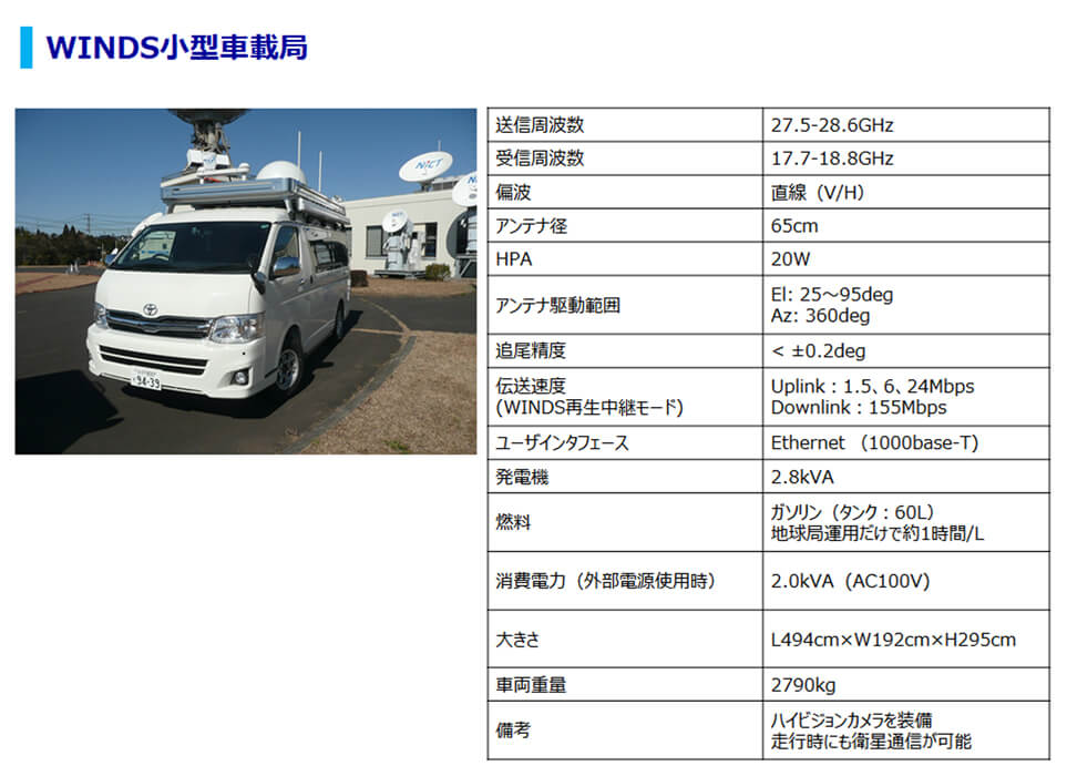 The small mobile vehicle earth station
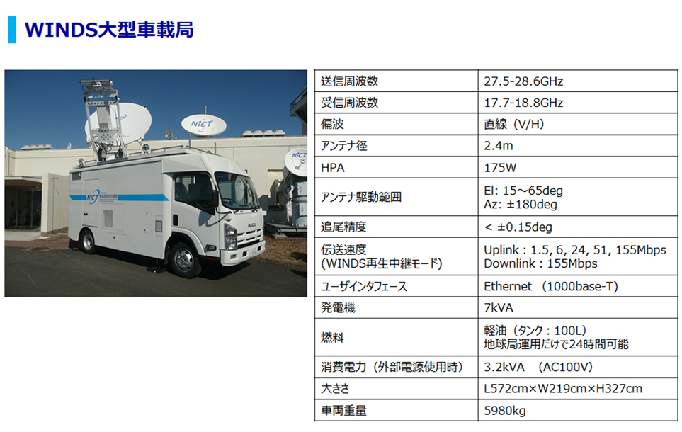 The large-scale in-vehicle earth station
 The on-vessel small earth station
Configuration of the Satellite On-board Switch
Signals from earth stations were received at the satellite and converted into IF signals. In the received IF switching network, three beams were selected and input to the satellite’s on-board high-speed switch.
In the switch, three demodulators (D-DEMs) each received a single beam. Each D-DEM was composed of three demodulating units capable of rates from 1.5 to 51 Mbps. To receive a 1.5-Mbps signal, a signal of 14 channels was separated by a frequency divider and demodulated by a single demodulating unit.
The baseband data demodulated at each D-DEM were accumulated in reception line buffers. Data for three systems were synthesized in a multiplexer and sent to an input buffer. Information from the earth stations was transmitted as a group of ATM cells. A switch core allocated each ATM cell based on its header information. Cells sharing the same destination were stored together in an output buffer. This ATM core had a capacity to handle up to 2.5 Gbps of data.
The transmission destinations for inclusion in the ATM headers were defined in advance at the Network Management Center(JAXA Tsukuba Space Center). The data to be transmitted was allocated by a distributor to beams and sent to transmission line buffers.
The MODs modulated data into TDMA burst signals for each beam and for output at the timing indicated by a switch controlling subsystem. The switch controlling subsystem controlled the transmission IF switch network on a burst basis, and in the switch network, the TDMA burst signals were allocated to beams based on destination.
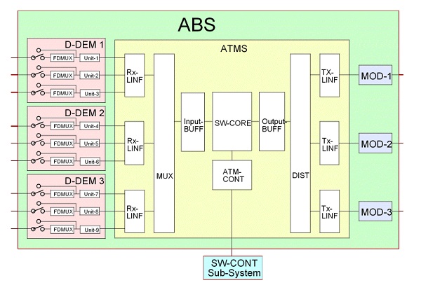 Configuration of the on-board high speed switch
Frequency Arrays for Regenerative Switch
The KIZUNA (WINDS) used Ka-band frequencies. Frequencies for uplinks from earth stations to the satellite ranged from 27.5 GHz to 28.6 GHz. Frequencies for downlinks from the satellite to the earth stations ranged from 17.7 GHz to 18.8 GHz.
For uplinks, the regenerative relay mode provided transmission rates from 1.5 Mbps to 51 Mbps. WINDS used lower half bandwidths. For transmission at 6.1/24/51 Mbps, the lower bandwidths were divided into nine parts—three groups of three channels each. A single beam was assigned to each group. For transmission at 1.5 Mbps, the same bandwidths (used for 6.1/24/51 Mbps) were divided into 14 parts.
For downlinks, the lower half bandwidths were divided into three parts, each allocated to a single beam, resulting in a transmission speed of 155 Mbps.
The non-regenerative relay mode(based on the bent pipe architecture) was used at two lines, the upper and the lower bandwidths for 622 Mbps, and at one full bandwidth line at 1,244 Mbps when using QPSK.
In cases in which the transmission power source was assured—for example, if the network consisted merely of a single large earth terminal and a satellite—it proved possible to use both regenerative and non-regenerative relay modes. If so, a regenerative relay mode was used for the lower half and a non-regenerative relay mode for the upper half.
In the TDMA method, it is also possible to make use of the full bandwidth by dividing it into slots.
 Frequency assign for regenerative relay mode
(Fu10 and Fd4 are for non-regenerative relay mode)
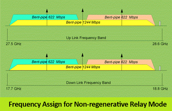 Frequency assign for non-regenerative relay mode

Support us

Collaborate with us

Use this technology
CONTACT
If you have any questions for the Space Communication Systems Lab., please contact us by using our inquiry form.
 Twitter
 Instagram
Copyright © 2019 Wireless Networks Research Center. All Rights Reserved.